Commodore 1540/1541 Disk Drive Modification (1984)
© 1984, 2013 by Dallas Denny and Rex Thompson
Source: Dallas Denny and Rex Thompson. (ca 1984). Commodore 1540/1541 disk drive modification.
Run magazine paid Rex and I for this article. I’m not sure if it ever ran. I think the magazine folded before it was scheduled.
I’ve substituted color photos for two of the original black-and-white images. I’m unsure of the year of submission, but it would have been between 1983 and 1985. I picked 1984.
Commodore 1540/1541 Disk Drive Modification
By Dallas Denny and Rex Thompson
Nashville Commodore Users Group
The Commodore VIC-20 and Model 64 are low-priced and reliable microcomputers with a wide variety of software and inexpensive peripheral devices. Both computers have many advanced features, but in order to keep prices competitive, it was necessary for Commodore Business Machines to leave out a number of convenient features which are available on more expensive microcomputers. Recently, Run Magazine featured a series of articles about adding some of these missing features to the VIC-20 computer. Unfortunately, improvements to the Commodore 1540/1541 disk drive weren’t mentioned. This article describes how to inexpensively modify the 1540/1541 drive so that different device numbers can be selected by means of external switches rather than by software or by disassembling the drives.
The 1540/1541 Drive
The Commodore 1540/1541 drive is an inexpensive mass storage device for the Commodore 64 and VIC-20 computers.
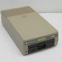
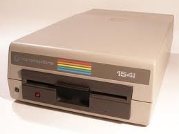
The Commodore 1541 single floppy disk drive is a mass storage device with an on-board controller (Photo 1). It replaced but is physically identical to the earlier 1540 drive. The 1540/1541 drive has its own RAM and ROM memory, making it independent of the computer’s memory. It stores over 170,000 characters on a 5 1/4 inch single-sided, double-density diskette. Up to four drives can be daisy-chained via the VIC or 64’s serial ports, allowing over 650,000 bytes of storage.
In order to utilize more than one 1540/1541 drive, it is necessary that all drives have different device numbers. Device numbers of 8, 9, 10, or 11 are allowed. The 1540/1541 comes preset from the factory as device 8. The rather cryptic manual which comes with the 1540/1541 tells of two ways of changing device number. One, a software method, is temporary. and must be done each time the drive or computer is turned on. To change the device number via the software method, one drive is turned off, and a program from the 1541 User’s Manual called “Disk Address Change” is run. This changes the device number of the drive which is left on to 9, 10, or 11, and then the other drive is switched back on; it remains device 8.
The second method involves physically opening the drive and cutting one or both of two jumpers on the main circuit board. Since the manual doesn’t provide a photograph or drawing of the jumpers, the novice can become easily confused when looking for them. After the jumpers are cut, the drive is reassembled, and the device number is permanently changed. Unfortunately, most software assumes that the available drive is device number 8. This means that in order to use the software, the physically altered drive must be repeatedly changed to the expected device number via the Disk Address Change program; this is time-consuming and annoying.
Changing Device Number Via Microswitches
If only a single drive is owned, there is no need to change device numbers. If a second drive is purchased, it is ordinarily changed to device 9. At times, however— for instance, when drive 8 is in the shop for repairs, it would be handy to assign a semi-permanent device number to a drive. Fortunately, there is a way to change device numbers via hardware which allows easy switching of device numbers without repeated disassembly of the drive. This method involves cutting the jumpers and bridging them with microswitches which can be installed on the outside case of the drive. The section which follows provides detailed instructions for doing this. A word of caution is advised, however. The soldering involved is delicate, and permanent damage to the drive could result from dropped globs of solder. The actual soldering should be done only by an experienced solderer with a low-wattage iron. Take the time to find someone with the right touch. Don’t be solder, but wiser.
Materials required are two single-pole, single-throw switches. Any switch can be used, but care should be taken in selection of switches which won’t be easily hit by accident, and which can fit into the limited space available on the case. We used Radio Shack Part Number 275-401, with a cost of $.89 the pair. About four feet of 22 gauge wire and several plastic wire ties are also needed. Tools required are a soldering iron of 40 watts or less, a sharp knife, a medium-sized Phillips screwdriver, a drill, a small file, and a lamp for illumination.
Cutting the Jumpers
To begin, be sure that there’s not a disk in the drive, then disconnect the power cord and the DIN plug which connects the drive to the computer. Turn the drive upside down and loosen the four screws which hold the two halves of the case together. Turn the drive right-side up, being careful not to lose the screws as they fall out of the holes. Lift off the top half of the case.

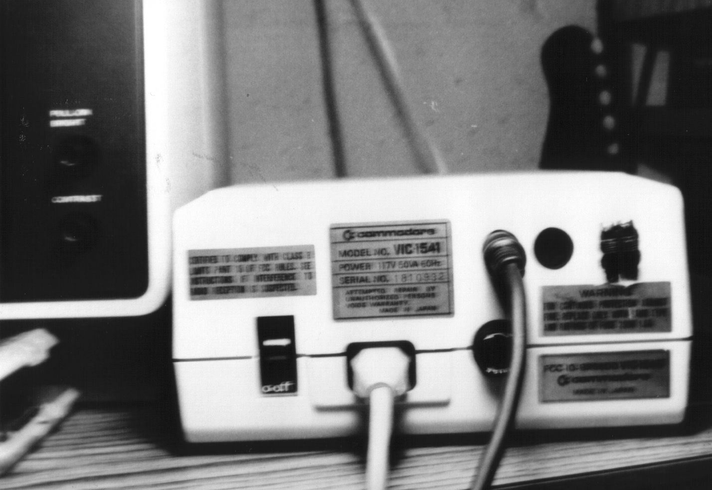
The Commodore 1540/1541 drive-rear view. Switches will be placed in the right upper portion, just to the right of the round DIN sockets. Note the manufacturer’s warning about unauthorized repairs.
Drill a ¼” inch hole in the top half of the case, about one inch from the left side and 1/2 inch from the top (Photo 2). The hole will be to the left of, and in line with, the round holes for the DIN connectors. When the hole is drilled, enlarge it with a file, being careful not to open the hole more than necessary for the switches to fit in. Fasten the switches in place with small screws. It is advisable to drill small holes to start the screws. A drop of glue in the screw holes will help hold them in place. Lay the case aside.
Now it’s time to cut the jumpers on the board. First, remove the pair of screws on the side of the metal housing which covers the main circuit board. Unplug the leader to the power light, and then remove the housing and lay it aside. The jumpers which must be cut are located on the left side of the board, about halfway towards the back, just outboard of the 6522 chip (Photo 3). Each jumper is a thin line of aluminum which connects two aluminum-colored semicircles. Use a knife to scratch through both jumpers. Then reassemble the drive, plug it in., and load a program from disk. If your drive is now device 11, the jumpers are cut properly.
Soldering Procedure
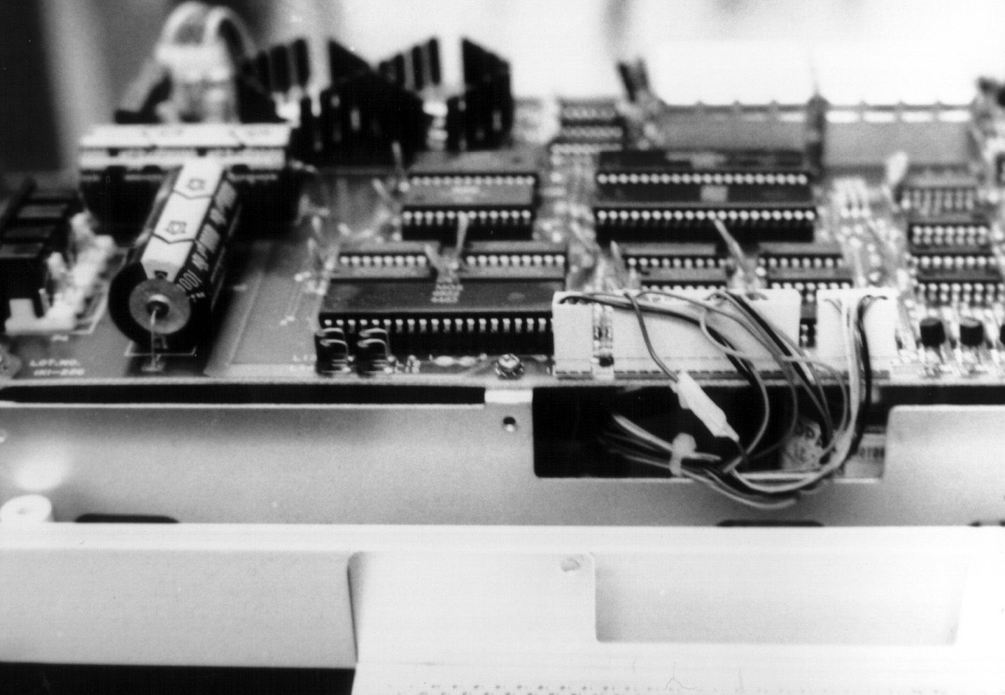
The jumpers which must be cut are located outboard of the 6522 chip. Each connects a pair of the small semicircles to the left of the screw which is visible in mid-photo.
After you have again disassembled the drive, cut the 22-gauge wire into two 12-inch and one 15-inch sections. Strip about 1/4 inch of insulation from one end of each wire. If you look closely at the jumpers that were cut, you’ll notice that two of the semicircles are connected. It doesn’t matter which of the connected semicircles you choose, but solder the longer piece of wire to one of the connected pads. Opposite the two connected pads are the two isolated pads. Solder each of the two remaining wires to one of the pads. At this point three of the four semicircles will have wires soldered to them.
Next, connect the free ends of the wires to the switches that are mounted in the case. First strip about 1/2 inch of insulation from the two short wires and then solder one of the two wires to one of the terminals on either switch. Next, solder the other short wire to the corresponding terminal on the other switch. Now the longer wire must be attached to the remaining terminals of both switches. You can either use a short piece of wire to join the two switches or you can strip enough insulation from the long piece to connect the terminals. if you choose the latter method, the bare wire should be insulated with nonconducting tape or heat shrink tubing.
Rear view of the 1540/1541 drive microswitches were installed. Later, screws were used to fasten the switches to the case. We lacked tools to make a cleaner cut in the case.
Remove the screw from the left rear of the circuit board and use a wire tie to secure the wires. This will help to prevent accidental disconnection of the wires from the circuit board.
Put the drive back together, and you’re in business. Simply by moving the toggles, you can change the device number from 8 to 9 to 10 to 11. Be sure to turn off the drive before moving the switches.
Photo Captions
Photo 1. The Commodore 1540/1541 drive is an inexpensive mass storage device for the Commodore 64 and VIC-20 computers.
Photo 2. The Commodore 1540/1541 drive-rear view. Switches will be placed in the right upper portion, just to the right of the round DIN sockets. Note the manufacturer’s warning about unauthorized repairs.
Photo 3. The jumpers which must be cut are located outboard of the 6522 chip. Each connects a pair of the small semicircles to the left of the screw which is visible in mid-photo.
Photo 4. Rear view of the 1540/1541 drive after the switches were installed. Later, screws were used to fasten the switches to the case.